Technology

Thanks to the extensive use of technology the CSLS is highly automated. All storage and building services engineering technology has been future-proofed to allow extension of the storage facility and is as sustainable as possible.

Speicherbibliothek von oben nach Nordosten
The CSLS viewed from the air looking north-east.
Unteres Wartungspodes mit Lagerbehälter
Lower maintenance platform with storage container.
KTG mit beleuchtetem LAM
Crane with illuminated load handling device.
Inertisierungs-Technik Totale
Inert-atmosphere equipment, full shot.

Storage technology

  • High-bay storage system for containers
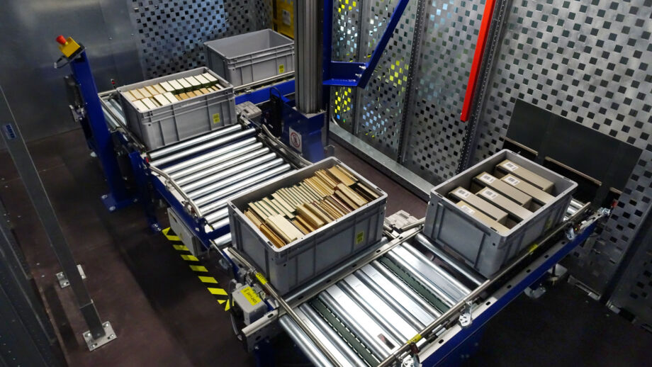
  • Containers
  • Storage and retrieval crane (STC)
  • Conveyor belt system
  • Vertical conveyor
  • 4 picking stations
  • 2 mobile picking stations
  • Warehouse management system (WMS)
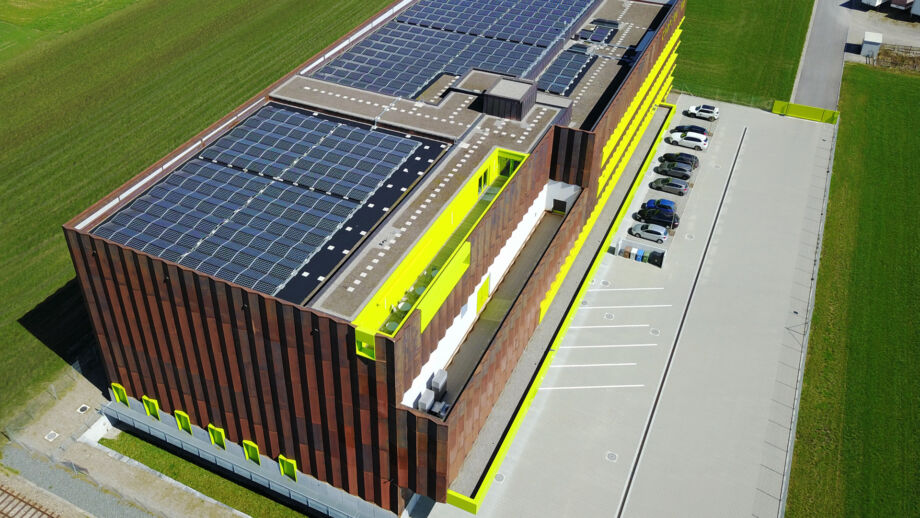
Storage an retrieval crane (STC)

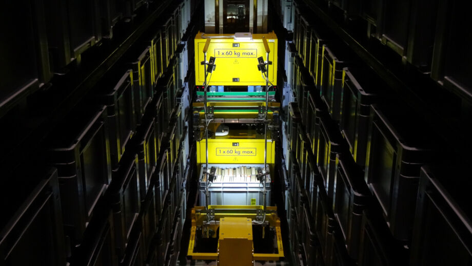
The storage and retrieval cranes (STC), one for each alley, retrieve containers which contain items ordered for loan or scans from the high-bay slots and replace them after use. They each have two load handling devices (LAM) arranged one above the other, making it possible to transport two containers at once. The acceleration of the STCs has been throttled to ensure optimum protection of the books.


  • Storage and retrieval crane (STC)
    Load handling deviceOne above the other
    Loadmax. 2×60 kg
    Travel speed4.0 m/s
    Travel acceleration0.8 m/s²
    Lifting speed1.0 m/s
    Lifting acceleration1.0 m/s²

Nitrogen production (inerting)

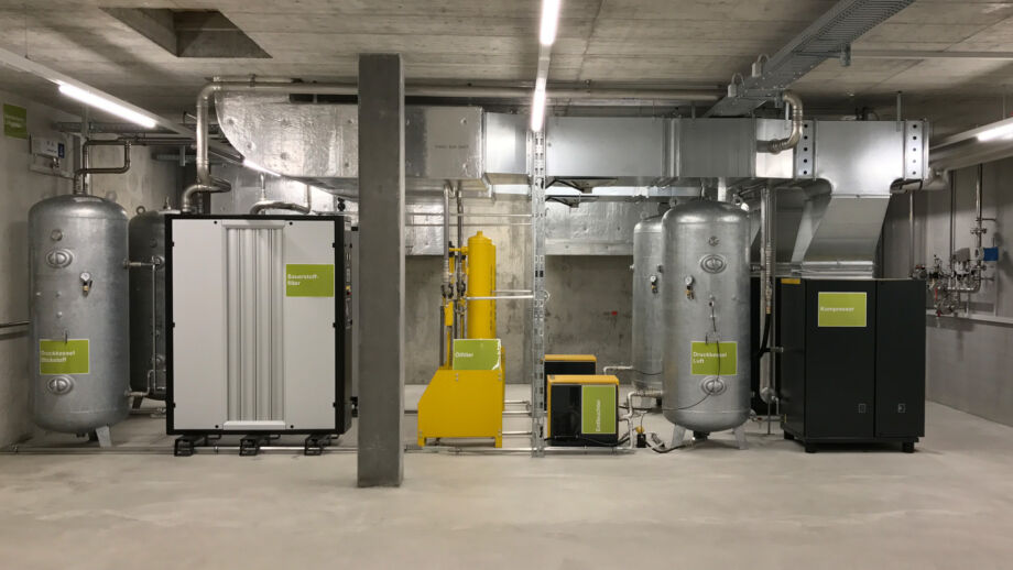
The oxygen content of the high-bay storage facility’s air is constantly reduced to 13.5 % to protect the storage area from fire. The nitrogen required for this process is produced on site by a plant with two lines operating in tandem and is introduced into the storage facility as required. The waste heat produced by the oxygen reduction plant is used in the heating system of the building.

  • Operating mode
    • Compressors turn ambient air into 8-bar compressed air stored in a compressed air tank.
    • The compressed air is de-humidified and oil residues are separated out.
    • An oxygen membrane filter removes and captures the oxygen.
    • The virtually pure nitrogen is temporarily stored in the compressed air tank and introduced into the high-bay storage facility as required.
    • The oxygen which captured by the oxygen filter is regularly discharged into the ambient air.
    • The plant is made up of two lines. Both lines operate simultaneously.
    • One line can maintain the amount of nitrogen in the storage facility at a constant level; when operating in tandem, both lines can reduce the amount of nitrogen.
    • The waste heat produced by the copressor is used to generate energy.

Environmental technology

  • The building was constructed to meet the Swiss “Minergie P” standard (not certified).
  • Embodied energy was avoided as much as possible.
  • The flat roof is fitted with a photovoltaic installation which produces 179 MWh/per year, about 88% of the energy used by the entire building in one year.
  • Heating is realised with geothermal probes and heat pumps in 60 of the 259 stabilising piles.
  • Waste heat from the oxygen reduction plant is used for heating.
  • The ventilation system includes heat and humidity recovery functions.